Teensy 4.1 Computer
The Teensy 4.1 Computer is more or less described by its name: Its a carrier board for the Teensy 4.1 which provides four USB ports, an Ethernet port, Hi-Fi audio, and several convenient expansion ports.
Detailed Specifications
USB:
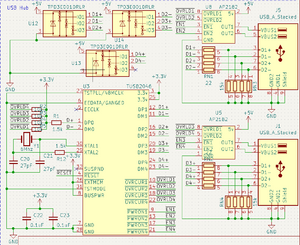
- TUSB2046 USB Hub, providing 4 USB A ports
- Each port has a maximum of 1.5A output - the port will shutdown due to overcurrent above this
- Board power provides a maximum of 2A to the 5v supply
- one should be aware of this when considering the power used by USB devices
Audio:
- I2S control connected to Teensy I2S 2
- PCM5102 ADC for providing stereo sound
- OPA1688 for the amplifier
- 3.5mm audio jack, maximum 75mA per channel
- Separate ground, connected to main ground through a ferrite bead
- Separate 3.3v and 5v supplies from linear regulators to reduce noise
- Note: 5v line will come from main 5v rail if only powered from USB
Power:
- 2A 5v buck regulator (Exact part is the VR20S05)
- PMOS switches to prevent regulator backfeeding from USB and to control power flow (U16, U17, and U18 on the PCB)
- External VIN accepted from 8v to 20v
- Separate 5v and 3.3v supplies for audio circutry
- Barrel jack and screw terminal connections for VIN
Expansion Ports
- I2S, SPI, I2C, and Serial expansion ports
- 5v-capable 8-bit parallel bus port, with 3-bit address, WR, RD, select, and WAIT lines
- Two larger expansion ports, each providing a 3.3v compatible 8-bit parallel bus, various protocols like I2C and SPI, power, and GPIO
The Audio Circuit
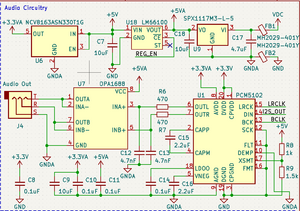
The Teensy 4.1 is connected to the audio circuit via the Teensy's I2S 2 port. This connection goes to the PCM5102 ADC. As is recommended in the PCM5102's datasheet, filtering is added to the output, however the filter used on this board is a bit stronger, using a 4.7nF capacitor instead of the 2.2nF capacitor recommended in the datasheet. The filter cutoff is still far above human perception, at 72kHz, and should filter high frequency noise a bit better. The connection to the OPA1688 is DC, not AC, coupled, but this is according to the recommendations in the OPA1688 datasheet. The gain of the amplifier is configured to be 1, so the output voltage of the amp should match the ADC's output voltage, and be in the range of 0v to 3.3v. A voltage divider is used to activate the PCM5102's soft mute function when the 5v line drops, which is designed to prevent any pops in the audio when the power is disconnected.
The circuit was designed with audio quality, but not energy efficiency, in mind. The circuit may sink as much as 400mA from VIN, and an additional 40mA from the main 5v line. However, when the audio circuit is idle, it should be less than 50mA all together. The 3.5mm audio jack can provide a maximum of 75mA per channel.
Example Code:
#include <Audio.h>
#include <SD.h>

// GUItool: begin automatically generated code
AudioPlaySdWav           playSdWav1;     //xy=719,389
AudioOutputI2S2          i2s2_1;         //xy=892,388
AudioConnection          patchCord1(playSdWav1, 0, i2s2_1, 0);
AudioConnection          patchCord2(playSdWav1, 1, i2s2_1, 1);
// GUItool: end automatically generated code

void setup() {
  Serial.begin(115200);
  AudioMemory(10);

  if (!(SD.begin(BUILTIN_SDCARD))) {
    // stop here, but print a message repetitively
    while (1) {
      Serial.println("Unable to access the SD card");
      delay(500);
    }
  }

  Serial.println("Playing audio.wav...");
  playSdWav1.play("audio.wav");
}

void loop() {
  // Do nothing forever
}

