Difference between revisions of "Teensy 4.1 Computer"
(Change size of mechanical measurements image) |
(Fix mechanical measurements header size) |
||
| Line 424: | Line 424: | ||
The card connector was designed to interface with cards for the Z80 computer I previously built, and has a compatible pinout. |
The card connector was designed to interface with cards for the Z80 computer I previously built, and has a compatible pinout. |
||
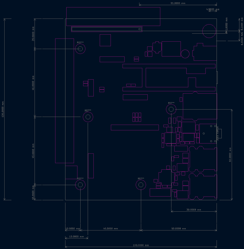
| − | + | == Mechanical Measurements == |
|
[[File:Teensy4.1 desktop measurements.png|Board measurements|854px]] |
[[File:Teensy4.1 desktop measurements.png|Board measurements|854px]] |
||
Latest revision as of 15:18, 30 July 2024
The Teensy 4.1 Computer is more or less described by its name: Its a carrier board for the Teensy 4.1 which provides four USB ports, an Ethernet port, Hi-Fi audio, and several convenient expansion ports.
Detailed Specifications
USB:
- TUSB2046 USB Hub, providing 4 USB A ports
- Each port has a maximum of 1.5A output - the port will shutdown due to overcurrent above this
- Board power provides a maximum of 2A to the 5v supply
- one should be aware of this when considering the power used by USB devices
Audio:
- I2S control connected to Teensy I2S 2
- PCM5102 ADC for providing stereo sound
- OPA1688 for the amplifier
- 3.5mm audio jack, maximum 75mA per channel
- Separate ground, connected to main ground through a ferrite bead
- Separate 3.3v and 5v supplies from linear regulators to reduce noise
- Note: 5v line will come from main 5v rail if only powered from USB
Power:
- 2A 5v buck regulator (Exact part is the VR20S05)
- PMOS switches to prevent regulator backfeeding from USB and to control power flow (U16, U17, and U18 on the PCB)
- External VIN accepted from 8v to 20v
- Separate 5v and 3.3v supplies for audio circutry
- Barrel jack and screw terminal connections for VIN
Expansion Ports
- I2S, SPI, I2C, and Serial expansion ports
- 5v-capable 8-bit parallel bus port, with 3-bit address, WR, RD, select, and WAIT lines
- Two larger expansion ports, each providing a 3.3v compatible 8-bit parallel bus, various protocols like I2C and SPI, power, and GPIO
The Audio Circuit
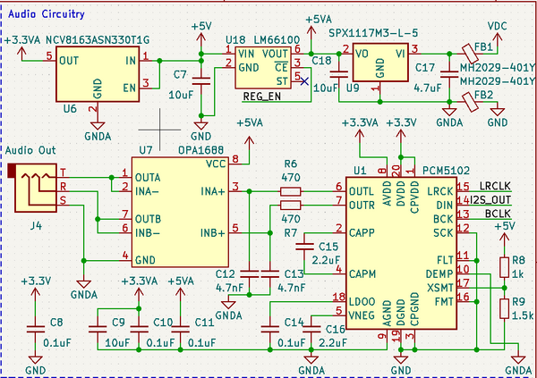
The Teensy 4.1 is connected to the audio circuit via the Teensy's I2S 2 port. This connection goes to the PCM5102 ADC. As is recommended in the PCM5102's datasheet, filtering is added to the output, however the filter used on this board is a bit stronger, using a 4.7nF capacitor instead of the 2.2nF capacitor recommended in the datasheet. The filter cutoff is still far above human perception, at 72kHz, and should filter high frequency noise a bit better. The connection to the OPA1688 is DC, not AC, coupled, but this is according to the recommendations in the OPA1688 datasheet. The gain of the amplifier is configured to be 1, so the output voltage of the amp should match the ADC's output voltage, and be in the range of 0v to 3.3v. A voltage divider is used to activate the PCM5102's soft mute function when the 5v line drops, which is designed to prevent any pops in the audio when the power is disconnected.
The circuit was designed with audio quality, but not energy efficiency, in mind. The circuit may sink as much as 400mA from VIN, and an additional 40mA from the main 5v line. However, when the audio circuit is idle, it should be less than 50mA all together. The 3.5mm audio jack can provide a maximum of 75mA per channel.
Example Code:
#include <Audio.h>
#include <SD.h>

// GUItool: begin automatically generated code
AudioPlaySdWav           playSdWav1;     //xy=719,389
AudioOutputI2S2          i2s2_1;         //xy=892,388
AudioConnection          patchCord1(playSdWav1, 0, i2s2_1, 0);
AudioConnection          patchCord2(playSdWav1, 1, i2s2_1, 1);
// GUItool: end automatically generated code

void setup() {
  Serial.begin(115200);
  AudioMemory(10);

  if (!(SD.begin(BUILTIN_SDCARD))) {
    // stop here, but print a message repetitively
    while (1) {
      Serial.println("Unable to access the SD card");
      delay(500);
    }
  }

  Serial.println("Playing audio.wav...");
  playSdWav1.play("audio.wav");
}

void loop() {
  // Do nothing forever
}
USB Ports
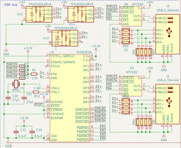
The Teensy 4.1's builtin USB port is connected directly to a TUSB2046 IC, which is a USB hub and provides four downstream ports. Each port has overcurrent protection, with a maximum allowed current of 1.5A. There are also TVS diodes on all USB data lines on the downstream ports, provided by three TPD3E001DRLR ICs. Other than that, each downstream USB port has two 15k pulldowns - one on each data line.
Example Code:
The best example is found in the Mouse_KeyboardBT example from the USBHost_t36 library, which is included in the TeensyDuino package. For convenience, I have included a stripped down version of it below:
#include "USBHost_t36.h"

USBHost myusb;
USBHub hub1(myusb);
USBHub hub2(myusb);
KeyboardController keyboard1(myusb);
KeyboardController keyboard2(myusb);
USBHIDParser hid1(myusb);
USBHIDParser hid2(myusb);
USBHIDParser hid3(myusb);
USBHIDParser hid4(myusb);
USBHIDParser hid5(myusb);
MouseController mouse1(myusb);

BluetoothController bluet(myusb);   // version assumes it already was paired

USBDriver *drivers[] = {&hub1, &hub2, &keyboard1, &keyboard2, &bluet, &hid1, &hid2, &hid3, &hid4, &hid5};

#define CNT_DEVICES (sizeof(drivers)/sizeof(drivers[0]))
const char * driver_names[CNT_DEVICES] = {"Hub1", "Hub2", "KB1", "KB2", "Bluet", "HID1" , "HID2", "HID3", "HID4", "HID5"};

bool driver_active[CNT_DEVICES] = {false, false, false, false, false, false, false, false, false, false};

// Lets also look at HID Input devices
USBHIDInput *hiddrivers[] = {&mouse1};

#define CNT_HIDDEVICES (sizeof(hiddrivers)/sizeof(hiddrivers[0]))
const char * hid_driver_names[CNT_HIDDEVICES] = {"Mouse1"};

bool hid_driver_active[CNT_HIDDEVICES] = {false};

BTHIDInput *bthiddrivers[] = {&keyboard1, &mouse1};
#define CNT_BTHIDDEVICES (sizeof(bthiddrivers)/sizeof(bthiddrivers[0]))
const char * bthid_driver_names[CNT_BTHIDDEVICES] = {"Keyboard(BT)", "Mouse(BT)"};
bool bthid_driver_active[CNT_BTHIDDEVICES] = {false};


bool show_changed_only = false;

uint8_t joystick_left_trigger_value = 0;
uint8_t joystick_right_trigger_value = 0;
uint64_t joystick_full_notify_mask = (uint64_t) - 1;

void setup() {
  while (!Serial); // wait for Arduino Serial Monitor
  Serial.begin(115200);
  myusb.begin();
  keyboard1.attachPress(OnPress);
  keyboard2.attachPress(OnPress);
}


void loop() {
  // check to see if the device list has changed:
  UpdateActiveDeviceInfo();

  myusb.Task();

  if (mouse1.available()) {
    Serial.print("Mouse: buttons = ");
    Serial.print(mouse1.getButtons());
    Serial.print(",  mouseX = ");
    Serial.print(mouse1.getMouseX());
    Serial.print(",  mouseY = ");
    Serial.print(mouse1.getMouseY());
    Serial.print(",  wheel = ");
    Serial.print(mouse1.getWheel());
    Serial.print(",  wheelH = ");
    Serial.print(mouse1.getWheelH());
    Serial.println();
    mouse1.mouseDataClear();
  }
}

void OnPress(int key)
{
  Serial.print("key '");
  switch (key) {
    case KEYD_UP       : Serial.print("UP"); break;
    case KEYD_DOWN     : Serial.print("DN"); break;
    case KEYD_LEFT     : Serial.print("LEFT"); break;
    case KEYD_RIGHT    : Serial.print("RIGHT"); break;
    case KEYD_INSERT   : Serial.print("Ins"); break;
    case KEYD_DELETE   : Serial.print("Del"); break;
    case KEYD_PAGE_UP  : Serial.print("PUP"); break;
    case KEYD_PAGE_DOWN: Serial.print("PDN"); break;
    case KEYD_HOME     : Serial.print("HOME"); break;
    case KEYD_END      : Serial.print("END"); break;
    case KEYD_F1       : Serial.print("F1"); break;
    case KEYD_F2       : Serial.print("F2"); break;
    case KEYD_F3       : Serial.print("F3"); break;
    case KEYD_F4       : Serial.print("F4"); break;
    case KEYD_F5       : Serial.print("F5"); break;
    case KEYD_F6       : Serial.print("F6"); break;
    case KEYD_F7       : Serial.print("F7"); break;
    case KEYD_F8       : Serial.print("F8"); break;
    case KEYD_F9       : Serial.print("F9"); break;
    case KEYD_F10      : Serial.print("F10"); break;
    case KEYD_F11      : Serial.print("F11"); break;
    case KEYD_F12      : Serial.print("F12"); break;
    default: Serial.print((char)key); break;
  }
  Serial.print("'  ");
  Serial.println(key);
}

//=============================================================================
// UpdateActiveDeviceInfo
//=============================================================================
void UpdateActiveDeviceInfo() {
  for (uint8_t i = 0; i < CNT_DEVICES; i++) {
    if (*drivers[i] != driver_active[i]) {
      if (driver_active[i]) {
        Serial.printf("*** Device %s - disconnected ***\n", driver_names[i]);
        driver_active[i] = false;
      } else {
        Serial.printf("*** Device %s %x:%x - connected ***\n", driver_names[i], drivers[i]->idVendor(), drivers[i]->idProduct());
        driver_active[i] = true;

        const uint8_t *psz = drivers[i]->manufacturer();
        if (psz && *psz) Serial.printf("  manufacturer: %s\n", psz);
        psz = drivers[i]->product();
        if (psz && *psz) Serial.printf("  product: %s\n", psz);
        psz = drivers[i]->serialNumber();
        if (psz && *psz) Serial.printf("  Serial: %s\n", psz);

        if (drivers[i] == &bluet) {
          const uint8_t *bdaddr = bluet.myBDAddr();
          // remember it...
          Serial.printf("  BDADDR: %x:%x:%x:%x:%x:%x\n", bdaddr[0], bdaddr[1], bdaddr[2], bdaddr[3], bdaddr[4], bdaddr[5]);
        }
      }
    }
  }
  for (uint8_t i = 0; i < CNT_HIDDEVICES; i++) {
    if (*hiddrivers[i] != hid_driver_active[i]) {
      if (hid_driver_active[i]) {
        Serial.printf("*** HID Device %s - disconnected ***\n", hid_driver_names[i]);
        hid_driver_active[i] = false;
      } else {
        Serial.printf("*** HID Device %s %x:%x - connected ***\n", hid_driver_names[i], hiddrivers[i]->idVendor(), hiddrivers[i]->idProduct());
        hid_driver_active[i] = true;

        const uint8_t *psz = hiddrivers[i]->manufacturer();
        if (psz && *psz) Serial.printf("  manufacturer: %s\n", psz);
        psz = hiddrivers[i]->product();
        if (psz && *psz) Serial.printf("  product: %s\n", psz);
        psz = hiddrivers[i]->serialNumber();
        if (psz && *psz) Serial.printf("  Serial: %s\n", psz);
      }
    }
  }
  // Then Bluetooth devices
  for (uint8_t i = 0; i < CNT_BTHIDDEVICES; i++) {
    if (*bthiddrivers[i] != bthid_driver_active[i]) {
      if (bthid_driver_active[i]) {
        Serial.printf("*** BTHID Device %s - disconnected ***\n", bthid_driver_names[i]);
        bthid_driver_active[i] = false;
      } else {
        Serial.printf("*** BTHID Device %s - connected ***\n", bthid_driver_names[i]); Serial.flush();
        bthid_driver_active[i] = true;
        #if 0

        const uint8_t *psz = bthiddrivers[i]->manufacturer();
        if (psz && *psz) Serial.printf("  manufacturer: %s\n", psz);
        psz = bthiddrivers[i]->product();
        if (psz && *psz) Serial.printf("  product: %s\n", psz);
        psz = bthiddrivers[i]->serialNumber();
        if (psz && *psz) Serial.printf("  Serial: %s\n", psz);
    #endif
      }
    }
  }
}
Known Issues:
- Version 1.1 of the board leaves TUSB2046's reset line floating. This can be remedied by connecting the TUSB2046's reset line to some other circuit, although this is error prone.
Power
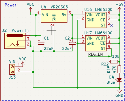
The computer's power supply accepts input from four primary sources:
- Barrel jack DC input, 8v to 20v, provides 2A to 5v line
- Screw terminal block, 8v to 20v, provides 2A to 5v line
- Teensy 4.1 micro USB port, 5v input, current limit depends on USB power source
- Expansion ports
- Direct to 5v line, only limited by source current. This allows one to surpass the typical 2A limit on the 5v line.
- Direct to VIN, accepts 8v to 20v. 5v line limited to 2A.
- Direct to 3.3v line, only limited by source current. This can be used to relieve stress from the Teensy 4.1's 3.3v regulator, if needed.
There are a few different power planes on the board:
- VIN, 8v to 20v input
- Feeds power to system 5v and audio 5v
- Audio 5v will come from system 5v if VIN is not provided
- System 5v line
- Provides power to the system 3.3v line and the audio 3.3v line
- If coming from VIN, this line is provided by a 2A switching regulator, which may have some noise.
- Is fed through PMOS power switches to downstream USB devices, functions as VUSB.
- System 3.3v line
- Provides power to the Teensy 4.1 and the TUSB
- Provided by the Teensy 4.1's internal 3.3v regulator from the system 5v line
- System Ground
- Connected to all circutry, with the exception of some of the audio circutry, which uses the audio ground instead
- Audio 5v line
- Provided by either a 5v linear regulator from VIN, or from the system 5v line if VIN is not provided
- Powers the OPA1688 audio amplifier
- Is not broken out to the rest of the board
- Audio 3.3v line
- Regulated by a linear regulator, getting input from the system 5v line through a ferrite bead
- Powers the PCM5102 audio ADC
- Is not broken out elsewhere on the board
- Audio Ground
- Connected to System Ground through a ferrite bead
- Connected to audio circutry
- Provides the ground used for the 3.5mm audio jack
- Not broken out elsewhere on the board
When providing power to the board, a few things should be kept in mind. First, for high quality audio, either VIN must be provided, or the system 5v line must be clean. The latter is generally much harder to do, so it is recommended to provide VIN if possible. For a clean system 5v line, generally it is to provide the system 5v line though a linear regulator instead. Adding more ceramic capacitors to the system 5v line can help as well. If providing power from an exteral board through an expansion connector, providing power to both the 5v and VIN lines can boost the maximum current of the system 5v line above 2A. If more than 2A is needed, for example for more current-hungry USB devices, then this may be desirable. Finally, there is a limit on the safe capacitence to be connected to the system 5v line for the 2A switching regulator to work normally. It is unadvisable to connect more than 800uF of external capacitence to the system 5v line, as it may interfere with that regulator. Although, there really usually is no reason to connect to much capacitence to that line.
If providing power to the system 5v line from an external source and the Teensy 4.1's USB port simultaneously, it is a good idea to include an ideal diode or similar circuit to prevent backflow from the USB port into your regulator, or vice versa, depending on your regulators characteristics. For this purpose LM66100 ICs can be used, as are used to protect the onboard switching regulator from the Teensy 4.1's USB port.
Capacitence by Power Plane:
- VIN:
- 22uF electrolytic
- 4.7uF ceramic (through ferrite bead)
- 26.7uF total
- System 5v
- 2.2uF on Teensy 4.1, ceramic
- 10uF onboard, ceramic
- Specific to onboard switching regulator: 22uF electrolytic
- 12.2uF total when external 5v is provided (Teensy 4.1 micro USB, expansion slots directly to 5v rail)
- 34.2uF total when onboard regulator is used
- System 3.3v
- 7.13uF from Teensy 4.1, ceramic
- 0.3uF onboard for decoupling, ceramic
- 7.43uF total
- System Ground
- 10.3uF ceramic
- 14.7uF ceramic (through ferrite bead)
- 44uF electrolytic
- Approximately 25.13uF on Teensy 4.1, ceramic
- 94.13uF total
- Audio 5v
- 10.1uF ceramic
- Audio 3.3v
- 10.1uF ceramic
- Audio Ground
- 27.2uF ceramic
- Connected to system ground through ferrite bead - technically connected to those capacitors as well.
Expansion Ports
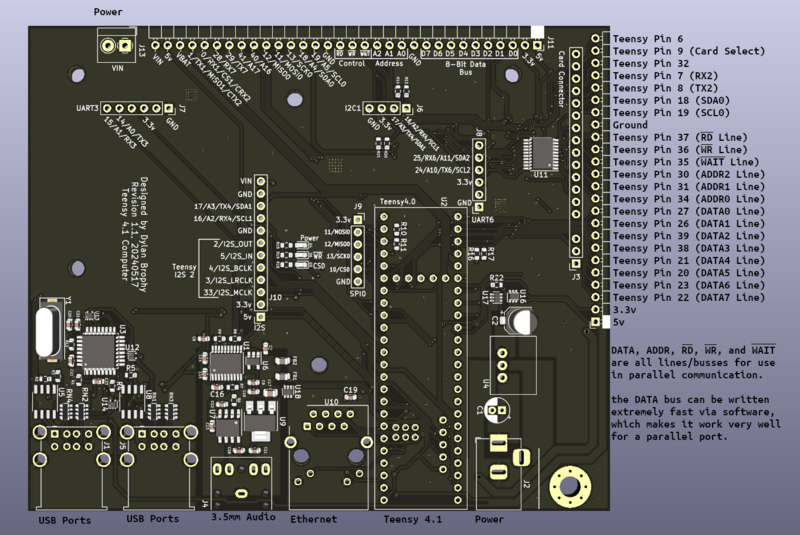
There are three large expansion ports on the Teensy 4.1 computer board, and 5 smaller ports. Here is a list, describing what each one breaks out:
- Largest expansion port on the back of the board (J11)
- Designed for large expansions to the computer system
- Exposes all power pins, including VIN, 5v, 3.3v, GND, and even the Teensy's VBAT line
- Numerous Teensy 4.1 pins: 0, 1, 11, 12, 13, 18, 19, 28, 29, 40, 41
- UART1
- UART7
- SPI0
- I2C0
- Analog inputs: A4, A5, A16, A17
- CRX2 and CTX2
- 3.3v-compatible 8-bit parallel bus
- Particularly useful for LCD displays and LCD display controllers, or any other parallel peripheral, for very high speeds
- Right-side expansion port (J12 - reference not shown on board revision 1.1)
- Designed for ATX-compatible expansions to the board
- Exposes 5v and 3.3v lines
- 3.3v-compatible 8-bit parallel bus
- Several Teensy 4.1 pins: 6, 7, 8, 9, 18, 19, 32
- UART2
- I2C0
- Analog inputs: A4, A5
- Card Expansion Port
- Designed to provide a card slot to fit in an ATX case. The card may provide IO to the front.
- Provides a 5v-compatible 8-bit parallel port. The pins are shared with the other parallel ports.
- The direction of all data pins are controlled by the control lines. Cannot use data line as input and output at the same time
- Controlled by write, read, and select lines. Select pin is pin 9, pulling it low will enable communication.
- Provides only a 5v line.
- I2S Expansion Port (J10)
- Provides an alternative to the 3.5mm audio output, and allows one to attach a microphone
- Breaks out I2S port 2
- Can be used to add a microphone alongside use of the 3.5mm audio jack
- Provides all power rails: VIN, 5v and 3.3v.
- Breaks out pins 16 and 17
- I2C1
- Analog pins A2 and A3
- UART4
- SPI0 Port (J9)
- Provided for SPI devices. Designed so that a card can be inserted to provide IO to the front of the board.
- Breaks out pins 10-13
- Provides 3.3v, but not 5v
- Breaks out SPI0
- UART6 Port
- This is a small port breaking out pins 24 and 25
- UART6
- Analog pins A10 and A11
- I2C2
- The port is designed so another board can provide IO to the front.
- The pinout is designed to be compatible with Sparkfun devices and serial pinouts
- Can be used also as an additional I2C port, and has the necessary 4.7k resistors connected
- Provides 3.3v and ground
- This is a small port breaking out pins 24 and 25
- I2C1 Port
- This is a small port breaking out pins 16 and 17
- UART4
- Analog pins A2 and A3
- I2C1
- Has the necessary 4.7k resistors connected
- The port is designed for internal devices, and is not designed to provide front-facing IO.
- Can be used also as an additional UART port
- Provides 3.3v and ground
- This is a small port breaking out pins 16 and 17
- UART3 Port
- This is a small port breaking out pins 14 and 15
- UART3
- Analog pins A0 and A1
- The port is designed for internal devices, and is not designed to provide front-facing IO.
- The pinout is designed to be compatible with Sparkfun devices and serial pinouts
- Provides 3.3v and ground
- This is a small port breaking out pins 14 and 15
About the Parallel Port
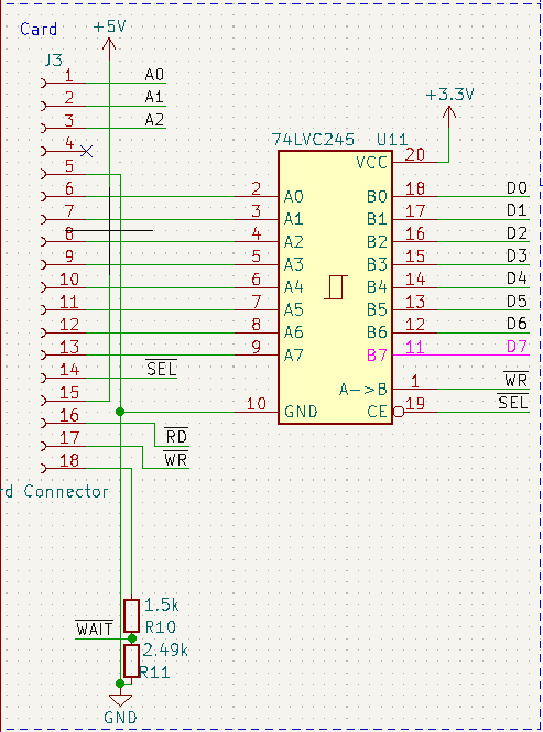
All three ports that provide parallel share the parallel pins WR, RD, and WAIT, as well as the busses ADDR and DATA. Each connected parallel device should use a separate select pin, however, with pin 9 being reserved as the card connector's select pin. WR, RD, and WAIT are all active low, and it is expected that all select lines also be active low. The address bus (ADDR, shown on the board as A0, A1, and A2) has three pins, allowing for three addresses per device. A parallel port is important to have because of the high bandwidth it provides. The Teensy can write this port extremely fast, thus allowing better framerates and draw times for connected graphics devices. I imagine there are other uses for this port as well.
As ADDR, WR, RD, and any select pins are all output-only from the Teensy, there is no level-shifting logic for them. For the WAIT line, there is a simple resistor voltage divider to take the 5v from the card connector down to 3.3v. There is only level-shifting logic provided for data lines on the card connector, so that 5v TTL devices and levels can be used with the card connector out of the box.
The card connector was designed to interface with cards for the Z80 computer I previously built, and has a compatible pinout.
